The water rocket: Launch tube thrust
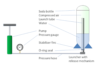
A launch tube inside the bottle does two important things:
- A tube with its open end above the water level keeps the water from spilling into the launcher pipe-work, leaving it inside the bottle for the rocket to use as reaction mass.
- It allows the bottle to gain velocity as the nozzle slides along the length of the tube, with negligible leakage of the water reaction mass.
There are a large number of international standards for 28 mm soda bottle necks. All the PET soda bottles I've seen look like PCO-1881 (PDF) evidenced by the slope of the flange that holds the bottle cap's retaining ring. In any case, all these standards have the same inner diameter: 21.74 mm. Let's assume 21.75 mm for wear and tear, as well as conservatism when calculating leakage. A standard ½-inch Schedule 40 PVC pipe has an outside diameter of 0.840” or 21.36 mm, which fits nicely into the bottle neck with about a 0.19 mm gap all around. The force acting on the bottle is simply the internal pressure multiplied by the cross-section area of the tube.
The pressure in the bottle doesn't remain constant as the rocket traverses the tube. We can assume it's constant for large-volume bottles, but for small-diameter bottles, a launch tube may occupy a significant fraction of the bottle volume. As the tube exits the rocket, it effectively increases the volume of air inside the bottle, reducing the pressure available for thrusting out the water. Because pressure is changing, the force and acceleration also change. However, because the leakage around the tube is negligible, we can assume the pressure decrease is linear. Therefore, we'll use the average pressure to get the average force, to arrive at an approximation of acceleration, and thereby get the final velocity the moment the bottle has left the tube and the water-thrust phase begins.
Conventions
This pages and those that follow about water rocketry use these conventions:
- In the formulas, I denote pressure using an uppercase \(P\) to for absolute pressure that includes atmospheric pressure (not just the pressure measured from a gauge), and lowercase \(p\) to denote measured pressure in a tank as measured with a pressure gauge.
- Equations are labeled by section:
- L1, L2,... for the "launch tube" equations
- B1, B2,... for the "ballistic flight" equations
- W1, W2,... for the "water thrust" equations
- A1, A2,... for the "air thrust" equations
- In all the formula symbol definitions, I include the units to be used, which are the meter-kilogram-second-kelvin unit system, even though in the text I may refer to pressure in PSI or length in millimeters.
Launch tube calculations
First we get the average pressure during traversal of the tube, using the adiabatic formula for pressure resulting from a change in volume. In this case, we use the total volume of air in the whole system, including the volume of air in the bottle (\(V\)) plus the volume of air in the launcher assembly and compressor hose (\(V_L\)). The total volume increases by the volume of the tube \(V_\text{tube}\) as the tube leaves the bottle and is replaced by the air in the system: $$P_0=P_\text{start} \left( \frac{V+V_L}{V+V_L+V_\text{tube}} \right)^\gamma\tag{L1}$$ $$P_\text{tube}=\frac{1}{2}\left( P_0 + P_\text{start} \right)\tag{L2}$$ where
- \(P_\text{start}\) = the absolute initial pressure \(p_a + p_e\) (Pa), in which
- \(p_a\) = ambient pressure (typically 101,325 Pa)
- \(p_e\) = excess pressure in tank above ambient (the pressure one would measure with a pressure gauge in a 1-atmosphere environment)
- \(P_0\) = the pressure at the end of the traversal, designated with a zero subscript to indicate that this is the initial pressure of the water thrust phase (Pa)
- \(P_\text{tube}\) = average pressure during traversal of the tube (Pa)
- \(V\) = volume of air in the bottle (m3)
- \(V_L\) = internal air volume of launcher assembly (m3); for a typical launcher with a 50-foot compressor hose, I estimate this to be about 1 liter
- \(V_\text{tube}\) = volume taken up by the launch tube (m3)
- \(\gamma\ = c_p / c_v\), where \(c_p\) and \(c_v\) are the specific heat capacities of air at constant pressure and constant volume, respectively. For dry air at 300K, \(\gamma=1.400\), but our air isn't dry. We assume air in a closed water-filled container is saturated at 100% relative humidity, in which case \(\gamma\) is lower. It comes out to 1.398 at 293K. However, we will see later that the best value is \(\gamma=1.34\), a fudged result obtained from calculating the heat contributed by water vapor during adiabatic expansion.
We're using an adiabatic expansion (isentropic) formula here, which accounts for a reduction in temperature (and therefore pressure) as the air expands. For the launch tube we could use the constant-temperature ideal gas law instead, in which the pressure changes proportionally with volume, but for consistency with the rest of the calculations, we'll use the adiabatic formula.
The volume of the tube \(V_\text{tube}\) can be the volume of a closed cylinder with the outer dimensions of the tube. This gives the most conservative result because the whole system volume is increased by the volume of this cylinder, contributing to a larger reduction in pressure by the time water thrust begins. In reality, the tube's volume is much less because of the air core inside it, which remains in the bottle after the tube exits. The pressure in this core is maintained by the pressure inside the launcher plumbing, which can involve 50 feet of hose in addition to the PVC launcher pipes. There may be an extra liter or so of pressurized air just in the plumbing outside the bottle.
The average force on the tube, acceleration, traversal time, and velocity when the tube exits, are, respectively: $$F = A_\text{tube} P_\text{tube}$$ $$a=\frac{F}{M_0}$$ $$t_\text{tube}=\sqrt{\frac{2H_\text{tube}}{a}}\tag{L3}$$ $$v_0=a \cdot t_\text{tube}\tag{L4}$$ where
- \(A_\text{tube}\) = the cross section area of the tube (m2)
- \(M_0\) = the initial total mass of the rocket including water (kg)
- \(H_\text{tube}\) = the height of the tube (m)
- \(t_\text{tube}\) = time to traverse the length of the tube (sec)
- \(v_0\) = the rocket's velocity at the end of the traversal, designated with a zero subscript to indicate that this is the initial velocity of the water thrust phase (m/sec)
So that gives us velocity at the start of the water thrust phase (ignoring wind resistance which is negligible here). That's one of the two initial conditions we need to start the water thrust calculations. The other initial condition we need is the pressure \(P_0\), calculated from equation (L1). That calculation, however, assumes no water leakage. There is some leakage around the launch tube. The leak actually sprays out under pressure, imparting some thrust to the rocket. We're neglecting the leak's contribution to thrust and acceleration for simplicity. This additional thrust is more or less canceled out by friction losses as well as the loss of pressure due to the leak. However, we do need to calculate the amount of water that leaked out, so that we have an accurate pressure and water volume with which to begin the water thrust phase. To do that, we need to know the the water mass flow rate of the leak during the time traversing the tube. Calculation of mass flow rate is also needed for the water thrust phase, so we'll do that in the next installment.
Another approach
Some months after I figured out the calculations above, I found a paper written in 2002 by Dean Wheeler, Professor of Chemical Engineering at Brigham Young University, that presented an exact analytical solution for velocity along a launch tube, not as a function of time, but as a function of position (neglecting water leakage and atmospheric drag). Adapting equation 18 in that paper to the notation used here, the velocity of the rocket upon traversing a distance \(y\) along the launch tube is: $$v_\text{tube}(y)=\sqrt{ \frac{2P_\text{start}(V+V_L)}{M_0(1-\gamma)} \left[\left(\frac{y A_\text{tube}}{V+V_L}+1\right)^{1-\gamma} -1\right] -2y\left(\frac{P_a A_\text{tube}}{M_0}+g\right) }\tag{L5}$$
Then, plugging \(y=H_\text{tube}\) into this function, we get for velocity, traversal time, and acceleration at the height of the tube: $$v_0=v_\text{tube}(H_\text{tube})\tag{L6}$$ $$t_\text{tube}=\frac{2 H_\text{tube}}{v_0}$$ $$a=\frac{v_0}{t_\text{tube}}$$
Equations (L4) and (L6) yield quite similar results, less than 0.5% different, with L6 being slightly more conservative. Both approaches neglect velocity reduction due to pressure loss from leakage and atmospheric drag, but this is compensated by the fact that the leakage also provides some additional thrust.
References
- ↵ Isentropic Compression (or expansion), NASA Glenn Research Center.
- ↵ GSK Wong, TFW Embleton (August 1984): Variation of specific heats and of specific heat ratio in air with humidity. J. Acoust. Soc. Am. 76 (2). DOI: 10.1121/1.391597.
- ↵ Dean R Wheeler (2002): Modeling the Thrust Phase version 0.6. From Water-Rocket Thrust Equations.

Comments
Post a Comment