Building the strandbeest

Some years ago I visited the Exploratorium in San Francisco, where I saw an impressive work of kinetic art, a large mechanical contraption with many articulated legs made from PVC pipe. It walked easily when gently pushed. Kids would take turns in groups pushing it back and forth in a parking lot.
This was my first exposure to a strandbeest (Dutch for "beach beast"), a name given by the artist Theo Jansen to his walking kinetic sculptures. The link in the previous sentence has a good video showing how easily the mechanism walks. It looks almost alive. Theo Jansen has built huge strandbeesten powered by wind that walk down beaches while waving or spinning parts of themselves in the breeze.
Click here to skip down to assembly instructions
3D printing a strandbeest

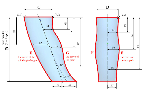
Leg proportions for Theo Jansen's strandbeest.
When we got a 3D printer in our home, I began thinking about how I would build one of these mechanisms myself. I found a few attempts already published on Thingiverse, but I perceived problems in all of them, such as: requiring support structure to print, asymmetrical joints, designs that haven't proven to be printable, too flimsy, too blocky-looking, or providing just STL files without CAD files for customization.
So, armed only with OpenSCAD and the linkage lengths pictured on the right, I set out to design my own strandbeest from scratch, without the deficiencies I perceived. My requirements were:
- Designed completely in OpenSCAD
- No asymmetrical joints
- All extrusion profiles use graceful curves, no straight lines
- The widest leg segment (which I call a "bone", specifically bone "c" in the diagram) connects the central frame to the foot, for better stability
- All parts are printable without support
- All parts snap together, no glue or fasteners needed

Typical breaking of snap clips when printed with PLA.
That last requirement turned out to be troublesome. The way I designed all the parts, the shafts for all the rotational joints must be printed vertically because you can't get a nice round shaft printed horizontally. Because the ends of each shaft must snap into something, the snap fittings must also be printed vertically — which is the absolute worst orientation to print snap fittings. Not only is PLA stiff and brittle, but the bending load applied to the fitting when snapping it into place can pull apart the plastic layers, breaking the fitting. Snap fittings should always be printed horizontally if possible. You can get vertically-printed snap fittings to work, but only with a material that adheres well to itself. Prusament PLA is barely sufficient; other PLA I have tried (particularly the shiny silk variety that I used in the photographs here) are horrible for this application.
In the picture at the top of this page, did you notice all the shiny metallic bronze parts? That's silk PLA material, and it's used only on the outward-facing surfaces of each bone. The rest of each bronze bone is printed with Prusament silver-gray PLA, which has better self-adhesion. You don't need a multi-color printer for this; you can simply set the slicer to pause the print two layers below where the shaft begins, at which time you can load a different filament.
If I were to print another strandbeest, I would use PETG for all parts with snap-fit shafts. It's sticky when melted and adheres well to itself, and it isn't brittle like PLA. PETG doesn't stick well to PLA, so I advise against combining them in the same part.
Getting the strandbeest parts
The OpenSCAD source and all STL files are available on my strandbeest model page:
- On Printables: www.printables.com/model/129102
- On Thingiverse: www.thingiverse.com/thing:4390692
Separate STL files are available for a crankshaft for 4 pairs of legs or 5 pairs of legs (each configuration uses different rotations of the crankshaft connector keys). The crankcase (frame) part needs to be printed once per leg pair. The leg bone STL file is for one leg only; it must be printed twice to get a pair of legs.

For each pair of legs, these parts should be printed with PETG. PLA can be used for the rest.
You can use the slicer for your printer to separate parts that you want in different colors. The following parts are safe to print with poor-adhesion PLA because they don't have vertical snap fittings:
- Knee bone (the upper triangular leg piece)
- Foot bone (the lower triangular leg piece)
- All crankshaft parts
- Crankcase end cap
- Any flat bone pieces having only holes in them
Otherwise, the other leg bones and crankcase (shown on the right) should be printed with PETG for good self-adhesion. You should print out a sampling of parts to check bearing tolerances and snap clip strength before printing everything.
Preparing the parts

The printed part may have multiple areas to file smooth: seams on shafts, bumps on hub spacers, burrs on part labels, and glitches in bearing holes. (Click to enlarge)
The STL files on Thingiverse were generated with tolerances that should allow for smooth rotation while still being snug. A part should be able to swing freely on a shaft. However, the printer often leaves small burrs in hub holes, and ridges on shafts where perimeters begin and end.
So you should take a small half-round file and do the following for all parts:
- With the rounded side of the file, lightly smooth the inside of all hub holes (not the snap-fit holes).
- With the flat side of the file, smooth the flat parts where they are labeled (all parts include engraved identifying marks, which sometimes leave raised burrs from nozzle retractions).
- The hub holes include built-in spacer washers that may also include burrs. The STL files have a layer or two of stacking tolerance but you don't want this to build up for the large stack of bones on the crankshaft, so make sure these washers are nice and flat.
- Flatten any ridges on shafts, including lightly filing the edges of the snap clips.
Check how well a part rotates around a shaft before assembling it permanently. If a hub sticks while passing over a snap clip but rotates freely when in its final position, it's fine.
Assembling the strandbeest
The instructions below show how to assemble this strandbeest with 4 pairs of legs:

The strandbeest legs are built in pairs. Each pair of legs consist of 26 parts that must be assembled in a specific order.
Every part also includes a mark on the inside flat surface, identifying the bone (B, C, J, etc. according to the leg segment diagram above), and in some cases there is another mark near a hub hole, indicating what bone shaft fits into that hub hole. Proper orientation of each bone is critical.
The illustrations below have parts colored like this:
- Gold indicates the next part to install
- Red-orange highlights the part that the next part snaps into.
- This indicates that you must press only on these two parts to snap them together. Don't snap a new part into the assembly without opposing pressure on the opposite part indicated in red-orange.
- Rotate the crankshaft as needed to provide enough space for your fingers to press on both parts.
- Silver-gray indicates bone parts already installed.
- Light cyan indicates crankcase and crankshaft parts already installed.
Click on any illustration to enlarge it, and then use your browser's "Back" button to return to this article.
1. Knee-and-foot assemblies
For each pair of legs, arrange two knees (triangle bones with three hub holes) and two feet (triangle bones with one sharp corner) along with the parts for two F bones. The F bone is the simplest bone, with a snap-fit shaft on each end of one part, and a hole on each end of the mating part.

The concave curve of the knee must face the foot as shown. Use the marks on the foot and knee bones to see which holes connect to bone F.
2. Crankshaft input
Each crankshaft section requires an input from the previous section. In the case of the first pair of legs, the crankshaft STL file includes a circular piece for the first crankshaft input. Place this shaft-up on a surface and slip the crankcase over it.

Orient the crankcase as shown, with the two angled cross arms angling toward you. The top of the crankcase is the shaft furthest away from you, and the bottom of the crankcase is the shaft nearest to you.
3. Crankshaft
Press the long crankshaft (bone M1) into the crankshaft input key. This is a friction fit, and it fits only one way. When you assemble higher layers, be sure to hold the previous crankshaft part with a finger before pushing the crankshaft down onto the key.

4. Stack of bones
Now we'll start building up a stack of 8 bone pieces on the crankshaft.
Layer 1
Find the bone pieces C and J that have shafts on them. They are engraved with a label, and the hub holes of each are labeled with the piece to which it connects.
Slip the J hub onto the crankshaft M1.
Slip the C hub onto the right-side shaft of the crankcase.

Layer 2
Find the bone K part with only hubs, no shafts. Slip the hubs over the crankshaft and the end of bone C. Be sure to orient it correctly with the small bent end on bone C.

Layer 3
Install one of the knee-foot assemblies you built in step 1. The knee hub holes slip onto the bone J shaft and the right-side crankcase shaft. The foot hub hole slips onto the bone C shaft.
In this layer, also install the left-side bone J and bone C parts, similar to layer 1.

Layer 4
Find a bone K part that has shafts, not just hub holes as used in layer 2. The shafts on this part don't slip into hubs; they are solely for snapping together the mating bone K part later (both mating parts have hub holes on each end). Slip the hubs over the crankshaft and the end of left-side bone C. Again, orient it with the small bent end on bone C.

Layer 5
Now install the other the knee-foot assembly you built in step 1. The knee hub holes slip onto the left-side bone J shaft and the left-side crankcase shaft. The foot hub hole slips onto the left-side bone C shaft.
In this layer, also find the bone K part with shafts, and snap it onto the right-side bone K installed in layer 2. Try not to touch anything else besides the two parts you are squeezing together. Rotate the crankshaft if needed to make room for your fingers.

Layer 6: Complete right leg
Snap on the mating parts to bones C and J as shown. This completes the right leg bone assembly.

Layer 7
Snap the final bone K part onto its left-side counterpart as shown.

Layer 8: Complete left leg
Finally, snap the remaining bones C and J pieces onto their mates as shown. This completes the left leg bone assembly.

5. Spacers
Install the two thick spacers as shown. They should expose the top of the snap clip on the crankcase shafts.
If you carefully filed off the burrs from all of the bearing spacers on all the bones, there should be sufficient room left over for the washer (which is printed with the crankshaft parts) to fit on the shaft with 1 print layer of vertical height to spare. When the crankshaft part is installed in the next step, the washer shouldn't squeeze the stack of bones together. If it does, I suggest either filing down the washer to give it more vertical clearance, or eliminating it (which risks the crankshaft running into that last bone J part if the crankshaft isn't completely straight).

6. Crankshaft end
Each of the M2 crankshaft parts are labeled M2 on one side, and numbered on the other side: 1 for the first leg pair, 2 for the second leg pair, and so on. In most cases they are all identical, but depending on the leg configuration, the order matters because the keys on the end of each M2 part can be oriented differently. The 6-pair configuration is an example of this.
Press-fit the M2 part over the long shaft key. It fits only one way.

Squeeze with one finger on the end of the M1 long shaft and the other finger on the M2 part. Rotate the crankshaft if you need to give some room for your fingers.
7. Done with one leg pair!
Congratulations. One leg pair has been assembled.

Now we must cap it off with the crankcase for the next pair of legs.
8. The next crankcase
Snap the next crankcase onto the previous crankcase, to start building the next pair of legs.

8. The next crankshaft
It is tempting to push the next M1 crankshaft onto the key without manually applying pressure to the previous M2 part just below it. Don't do this! BE CAREFUL how you apply pressure! Rotate the crankshaft to give your fingers room to squeeze only these two parts together.

9. Finish assembly with end cap
In this assembly example we're building four pairs of legs as shown. When done, snap the end cap onto the last crankcase to close it. Apply pressure to the opposite crankcase to snap it into place.

Finished
Our strandbeest with four leg pairs is now complete.

And here is a version with five pairs of legs in real life:
Improvements?
This project was intended as a work of kinetic art. A secondary objective was to see if I could design it completely in OpenSCAD. As printed, this strandbeest doesn't do anything except serve as an entertaining conversation piece. I was hoping that its friction, while pretty low, would be low enough for the device to walk down a slope, driven by its own weight. Possibly if I hung weights from the lower crankcase bars, this could work.
I also put a Lego axle socket in the crankshaft input disk, thinking that maybe I could adapt this for Lego robotics, but that would involve redesigning the crankcase to include a Lego platform — and the crankcase sections could no longer be printed without support. The crankcase dimensions would also have to be a multiple of Lego brick units.
I am pleased with the outcome. It's attractive and fun to drag around on a carpeted surface (it doesn't walk on a smooth surface; the feet points need something to grab). My son also thinks this was a really cool project to do on our printer.

Comments
Post a Comment